 kingpdc




product search
search
Standard PDC (polycrystalline diamond compact) drill bit drawings typically depict two interdependent systems: the external cutting structure—comprising blades, PDC cutters, and gauge pads—and the internal hydraulic network, consisting of diversion chambers, flow passages, and nozzles. Truly masterful design requires that the physical arrangement of the cutting teeth be perfectly aligned with the computational fluid dynamics (CFD) of the internal flow paths, thereby maximizing the rate of penetration (ROP). Many structural diagrams on the market fail to identify the thermal-degradation “dead zones” concealed within the fluid channels. Today, we’ll take a hard-hitting look at genuine mechanical design drawings and uncover the structural flaws that cause drill bits to prematurely fail in alternating soft‑hard strata.
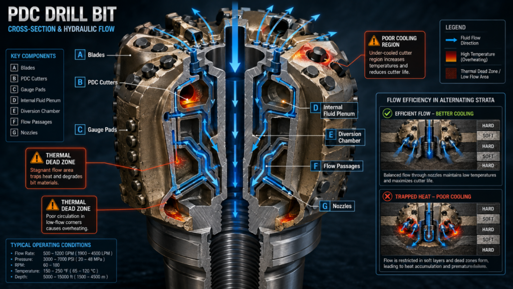
It is only when we move beyond conventional technical parameters that structural analysis truly begins. Designing a high‑performance drill bit requires striking a balance between cutting aggressiveness and hydraulic chip evacuation capability.
The back-rake and side-rake angles directly determine how aggressive the drill bit is and how much reaction torque it generates. Experienced R&D professionals will set the back‑dip angle within the range of 15° to 30°, based on the uniaxial compressive strength (UCS) of the target rock. At a smaller angle, cutting soft shale is as quick as slicing tofu; at a larger angle, it helps protect the diamond layer from chipping when drilling through hard limestone. The stabilizing shims are like the cornerstone of the entire structure, specifically designed to prevent lateral vibrations; after all, once such vibrations occur, the cutting teeth immediately chip and fracture.
The internal geometry determines just how effective the cooling is. The distribution chamber is responsible for receiving the high-pressure drilling fluid from the drill string and routing it through internal flow passages to the individual nozzles. If the runner design is subpar, “dead zones” with extremely low flow velocities will develop. Once mud accumulates in the dead zone, the immediate consequence is bit balling. During the review of internal drawings, the QA team rigorously scrutinizes the transition fillets along these flow paths, ensuring that fluid separation is completely eliminated.
I typically evaluate drill bits using the C.H.M. (Cutting-Edge, Hydraulics, Materials) method. This approach enables us to eliminate various potential failure risks well before the shop floor begins production based on the drawings.
If the cutting teeth are arranged too symmetrically, it can actually induce catastrophic harmonic vibrations. If the engineer places the cutting teeth on the opposing flanks at precisely the same radial position, the drill will naturally exhibit lateral resonant vibrations when it is rotated. How can this be resolved? Arranging the teeth in an “asymmetric” pattern can disrupt this resonance. Then, use specialized software to balance the drill bit’s forces, ensuring that any remaining unbalance is kept within 4% of the weight on bit (WOB). With just this one technique, when drilling through alternating soft and hard formations, it can significantly extend the drill bit’s service life.
The chip‑gutter volume must be at least three times the volume of the cut rock chips. We perform CFD simulations to accurately map the entire flow path: the fluid is ejected from the nozzle, flushes the tooth face, and then carries rock cuttings back to the surface along the annulus. If the internal-cone nozzle is positioned too far from the central axis, the very center of the drill bit will not be adequately cooled. Once the localized temperature of a cutting tooth exceeds 700°C, thermal degradation accelerates exponentially—the cobalt catalyst within the diamond layer expands upon heating, directly inducing microcracks in the cutting tooth.
| Metric | Standard Layout | Asymmetrical Layout | Impact on ROP |
|---|---|---|---|
| Nozzle Distribution | Uniform or near-symmetrical nozzle placement | Nozzles positioned according to local cutter density and hydraulic demand | Improves targeted cleaning and reduces wasted hydraulic energy |
| Center-Cone Cooling | May leave a low-velocity zone near the bit center if nozzles are positioned too far outward | Flow paths are adjusted to direct sufficient fluid toward the central cutting structure | Reduces center-cutter overheating and helps maintain cutting efficiency |
| Cutter-Face Cleaning | Similar flow intensity across all blades | Higher flow directed toward high-load and high-cuttings-generation zones | Limits chip accumulation and improves cutter-rock contact |
| Chip-Gutter Capacity | May use uniform gutter geometry regardless of local cuttings load | Gutter volume is sized according to expected cuttings generation, targeting ≥3× the cut-rock chip volume | Reduces clogging and improves cuttings evacuation |
| Flow Velocity Distribution | Greater risk of uneven velocity and hydraulic dead zones | CFD-optimized flow distribution minimizes stagnant and recirculation regions | More consistent cleaning can support higher sustainable ROP |
| Cuttings Evacuation | Cuttings may accumulate in low-flow areas before entering the annulus | Flow channels are shaped to rapidly transport cuttings from the cutter face into the annulus | Reduces regrinding of cuttings and wasted drilling energy |
| Cutter Temperature Control | Local hot spots may develop under poor cooling conditions | Cooling flow is concentrated around thermally stressed cutters | Helps prevent cutter temperatures from approaching critical thermal-degradation conditions |
| Thermal Degradation Risk | Higher when localized cutter temperature rises excessively | Lower when CFD-guided nozzle placement maintains effective cooling | Better cutter integrity helps preserve ROP over longer drilling intervals |
| Hydraulic Energy Utilization | Part of the pressure drop may be consumed by ineffective or poorly directed flow | Greater proportion of available hydraulic energy is directed toward cleaning and transport | Improves hydraulic efficiency without relying solely on higher pump pressure |
| Overall Drilling Performance | Stable in relatively uniform formations but less adaptive to uneven cutter loading | Optimized for non-uniform cutter loading, heat generation, and cuttings distribution | Potential for higher and more stable ROP, especially in demanding formations |
The matrix drill is particularly resistant to erosion, while the steel drill is superior in impact resistance. The tungsten carbide matrix drill bit will not blink when facing the high-speed drilling fluid mixed with abrasive solids, and its anti-erosion ability is a bar. In contrast, because the steel body substrate can withstand higher bending stress, its cutting edge can be made higher, and the chip groove can be dug deeper. In recent years, 3D printing technology has become more and more powerful. The research and development team can even directly print steel drill bits with bionic curved flow channels-this internal structure cannot be done by traditional five-axis CNC machine tools.
When checking the appearance and size, QA personnel must keep an eye on the place where the residual stress is piled up. When brazing, if the thermal expansion and contraction are uneven, micro cracks will appear at the bottom of the cutting groove. The quality inspector has to take a three-coordinate measuring machine (CMM) and card the protruding height of each cutting tooth one by one to see how much difference it is from the original CAD model. Remember: even if the shoulder cutting teeth only 0.5mm error, it will completely disrupt the load distribution of the entire drill, forcing the next teeth to bear the pressure they should not bear.
Take data from a drilling project in West Texas in 2025, which directly demonstrates how fragrant asymmetric design can be. In the same soft mudstone and hard limestone interlaced strata, we pulled out the standard six-wing symmetrical drill bit and the customized six-wing asymmetrical drill bit “one-on-one”. The result? The rate of penetration (ROP) of the asymmetric drill rose by 22%, from 85 feet per hour to 104 feet per hour. After tripping out, the wear situation is even more obvious: the asymmetric drill bit wears very evenly (passivation rating: 1-1-WT); On the other hand, the symmetrical drill bit, because it cannot hold down the lateral vibration, the shoulder cutting teeth are hit horribly (passivation rating: 4-4-SP).
What is the best back angle for a PDC bit?
It all depends on how hard the stone is. In order to pursue the maximum shear destructive force, the angle is generally 10 to 15 degrees. If you encounter hard stubble, it must be adjusted to 20 ° to 30 °, which can increase the impact resistance of the cutting teeth and prevent tooth chipping.
How does the flow rate affect the bit design?
If the flow rate is fast enough, the drill is not easy to paste into a ball (mud bag) and can cool the cutting teeth. The designer will carefully arrange the position of the nozzle, so that the water flow directly across the surface of the cutting teeth, to ensure that the debris is washed out of the chip groove before being “secondary grinding.
What is the difference between a matrix PDC bit and a steel body bit?
The matrix drill bit is burned out with tungsten carbide powder and binder, and its anti-erosion ability is ridiculously strong. The steel body drill bit is machined from high-strength alloy steel, which has better impact resistance and toughness, and the blade can also be made higher.
Why are bits easily scrapped in hard and soft staggered formations?
In such formations, the forces and torques on the drill bit can change dramatically in an instant. When drilling from soft shale into hard limestone suddenly, it will produce severe stick-slip vibration (stick-slip). At this time, if the drill bit is not well balanced, the diamond layer will be shattered on the spot.
How do engineers prevent drill bit mud?
It mainly depends on 3 methods: digging up the chip removal groove, calculating the most perfect nozzle position with CFD, and coating a special anti-mud coating on the drill bit to reduce surface friction.
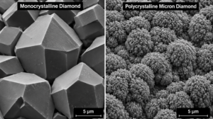
Discover Synthetic Polycrystalline Micron Diamond Solutions For Flawless Wafer Polishing And High CMP Yields.
View details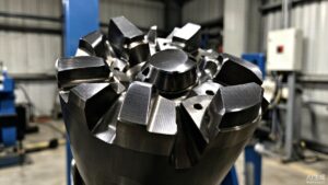
Explore How Polycrystalline Diamond (Pcd) Is Used In Oil And Gas Drilling, Geological Exploration, Stone Cutting, And Precision Machining.
View details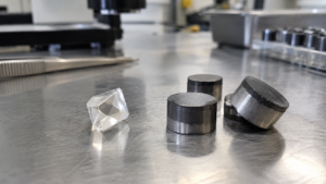
Single Crystal Diamond Vs Polycrystalline Diamond Explained With Hardness And Cutting Use Differences.
View details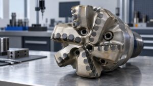
Learn what shapes pdc bit cost and compare quotes by design, cutter specification, quantity, quality, and delivery.
View details