 kingpdc




product search
search
When you encounter the phrase 4 1 2 reg pdc bit make up torque, the first point to clarify is the difference between a connection-level parameter and a cutter product parameter. A PDC cutter is a working element in the bit’s cutting structure, while a complete PDC bit also includes the bit body, blades, cutter pockets, connection, nozzles, flow paths, junk slots, gauge structures, and the upper connection. The phrase alone does not provide enough information to derive a universal torque value, so it should not be treated as a fixed value for a single PDC cutter.
The threaded connection at the top of the bit connects the PDC bit to the drill string or a downhole tool and transfers weight, torque, and fluid. The connection model belongs to the complete bit’s connection layer, not to the PDC cutter itself. Make-up torque should therefore be understood as a connection-level issue rather than a fixed cutter specification.
Torque is transmitted through the connection, bit body, blades, cutter pockets, and brazed joints before reaching the cutters. At the same time, the tangential force created as the cutters engage the rock is an important source of bit torque. The connection and the cutting structure are related, but they are not the same specification.
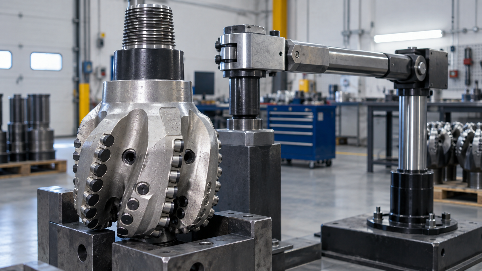
Torque is the rotational demand required to turn the bit and overcome cutting and friction resistance. WOB, RPM, torque, and ROP describe the response of the drilling-bit system; they are not fixed product parameters belonging to one PDC cutter.
The load on an individual cutter also changes with cutter count, radial position, depth of cut, angle, wear, rock conditions, and bit motion. The same cutter model can produce different cutting forces, temperatures, and failure modes when installed at different positions, angles, or exposures. The phrase alone cannot establish those conditions, so it cannot produce one torque value that is valid for every application.
Cutter specifications need to correspond to the bit design drawing and the cutter-position table. The table should distinguish the cutter number, blade number, bit region, radius, axial position, back rake, side rake, exposure, model, and orientation. When the same cutter model is used at different positions, the product specification may be shared, but the installation parameters still need to be matched to each position.
The cutter pocket and brazed joint also affect load transfer. Cutter outside-diameter tolerances need to match the pocket diameter and brazing gap. Pocket support and the brazed layer work together to carry the load, so connection reliability cannot be judged only from the nominal strength of the brazing alloy. Without position data, even a failure photo may not show whether the cause came from the cutter, bit structure, pocket, brazing, or operating conditions.
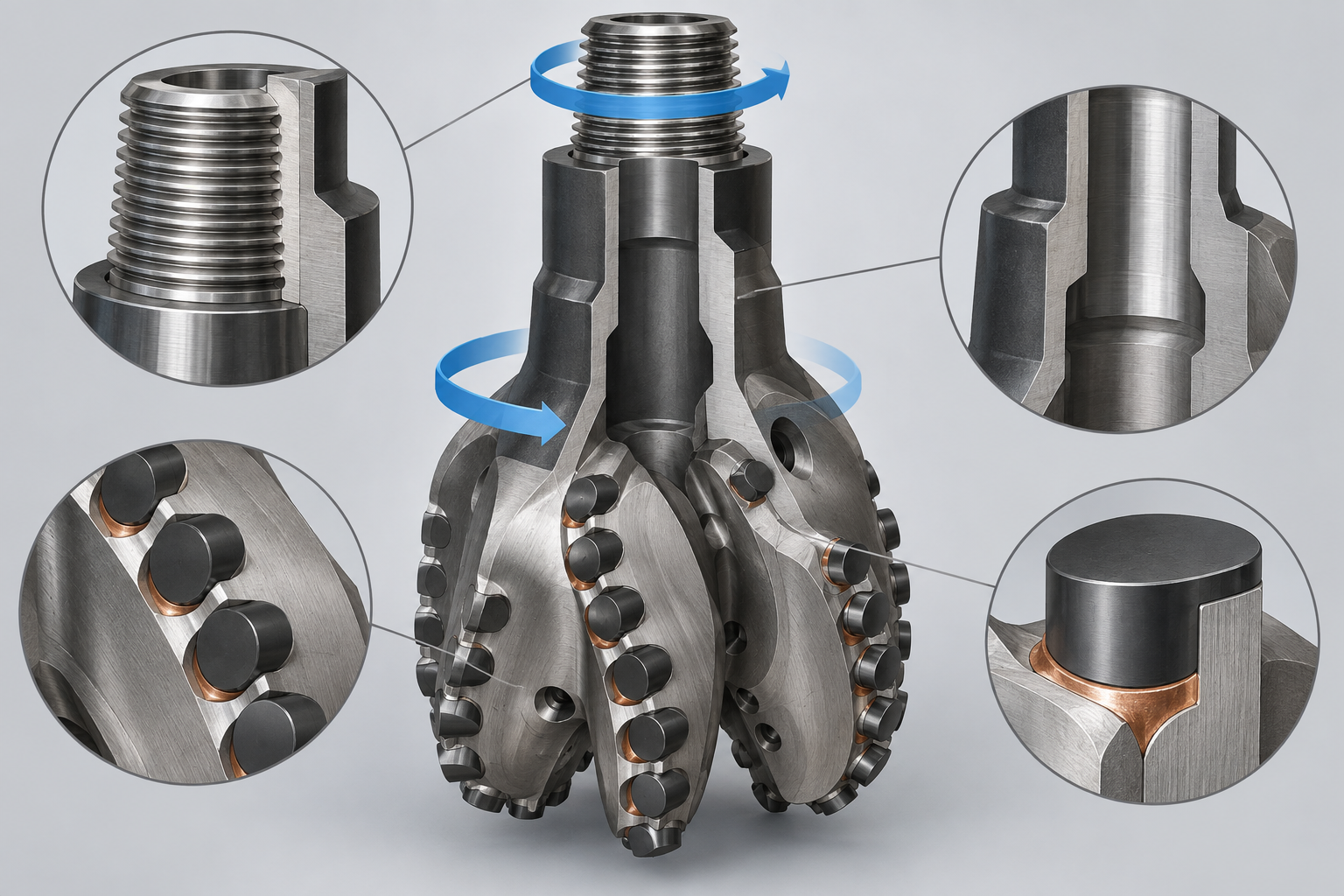
Torque and WOB fluctuations may indicate non-uniform cutting, stick-slip, or impact. They should be assessed together with vibration and downhole data. Bit balling or insufficient cleaning can reduce effective cutting, raise torque, and create heat buildup. These conditions should not be attributed to cutter material alone.
For that reason, 4 1 2 reg pdc bit make up torque is best treated as a connection-level question for a complete PDC bit. Without the connection identity, bit structure, cutter position, and operating conditions, a specific fixed value cannot be assigned, and connection torque should not be mistaken for a PDC cutter product parameter.
In high-stakes drilling environments—whether in oil and gas, mining, or geothermal applications—precision, speed, and durability are key to project success. In these harsh conditions, selecting the right drilling technology is crucial. PDC (P...
View details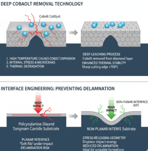
Maximize ROP With Our PDC Rock Cutter For Oil & Gas. Engineered For Impact Toughness & Thermal Stability.
View details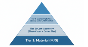
Pdc Bit Classification,Pdc Bit Nomenclature
View details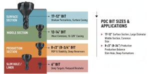
Guide To PDC Drill Bit Sizes From 3-1/2” To 26”. Match Standard Bits To API Casing Strings And Check Drift Diameters.
View details