 kingpdc


recherche de produits
recherche
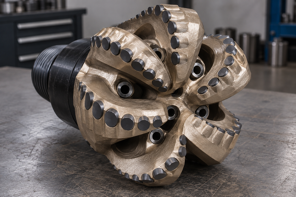
Looking at two PDC bits with the same outer diameter, the size and number of cutting teeth may be similar, but the wear after coming out of the well may be concentrated in completely different positions. The cause may not lie in the tooth itself. Whether it is installed in the center, nose or shoulder, the angle towards the rock, the height of the blade, and whether there is enough chip removal space around it will change the actual work it undertakes. When discussing PDC bit design, one cannot simply count the number of cutters.
Before design, the target well section is more important than a beautiful front view of the drill bit. Whether the formation is abraded, whether there is a hard interlayer, whether the well section requires orientation, and what is the available weight and speed range, all affect the choice of cutting structure. The rate of penetration, single-run footage, stability and cost per unit footage may also be tied to each other. If the goal is to reduce early collapse damage at a location, the same set of criteria should not be used for the program and the simple pursuit of higher footage speeds.
The old drill bit can provide more specific clues: which 1 row of teeth is ground flat first, what tooth number does the chipping occur, whether there is any abnormality in shoulder and gauge, and what is the torque and vibration state during drilling. Only knowing that "the previous drill was slow" is not enough to determine whether the next 1 should only increase the number of teeth or change the material.
The bit face from the center outward can generally be seen as a cone, nose, shoulder, and gauge zone. The path traveled by the inner cutting tooth is shorter and the outer path is longer, but it cannot be simply determined that the inner load is light and the outer load is heavy. The profile shape, whether the trajectories of adjacent teeth overlap, and the rock that each tooth actually cuts into will change the workload.
More blades can usually provide more installation positions and distribute part of the load; the price is that the space left between the blades for drilling fluid and cuttings may be narrowed. With fewer blades, the chip removal channel may be wider, but a single wing and a single tooth have to face different load and redundancy requirements. Therefore, "more wings are more durable" or "less wings are faster" can not be separated from the well section conditions directly. The tooth layout should also check whether there is an uncut core in the center and whether the trajectory from the shoulder to the gauge can be continuous, rather than just whether the front line is neat.
The caster angle affects the intrusiveness of the cutting teeth and the edge support, and the roll angle will change the lateral force and the direction of the debris leaving the working face. Both are defined together with the tooth position, profile and direction of rotation. A more aggressive installation may be more likely to cut into the rock and be more likely to expose chipping or dynamic instability problems during load changes; a more conservative installation may require more weight on bit. There is no 1 set of fixed angles for all strata and all tooth positions.
The exposed height is the geometric position of the tooth relative to the blade and is not equal to the actual depth of cut when drilling. More exposure may make room for cuttings, but it also increases the arm of force borne by the exposed part of the base. Deeper burial, increased support, blade friction and debris passage may become problems. The relative height between the main tooth, the backup tooth and the depth limiting element also needs to be checked, because after the main tooth is worn, the teeth that were not involved in the cutting may start to bear.
When selecting flat teeth, roof teeth, double chamfers or other special-shaped teeth, the name is only the starting point. What really needs to be written clearly is the geometry, size, chamfer, material, installation direction and responsible tooth position of the working face. If the same tooth shape is moved to another blade, the effect may be different. The different cutting tooth specifications provided by Feder can be used to discuss the selection, but the field performance of the entire drill cannot be inferred from the product name alone.
Where the tooth cuts out the debris, the nozzle and runner must consider how to carry the debris away from the location. Increasing the number of teeth, increasing the density of teeth or adding backup teeth may occupy the flow space. Only look at the total pump capacity and total pressure drop, without checking the local cleaning near the center, nose, shoulder and gauge, which is easy to miss the risk of mud bag, repeated cutting or local heating. Mechanical tooth arrangement and hydraulic layout should be adjusted in synchronization.
The tooth position, angle and exposure on the drawing need to be reviewed after the tooth socket is processed, assembled and brazed. In particular, the direction of the requirements of the shaped teeth, installed reverse or deflection, it may change the expected working edge. When testing a new bit, the total footage should not only be recorded; the operating parameters, formation intervals, vibration, reasons for tripping out and tooth-by-tooth wear should all correspond to the specific design version.
The next 1 version of the revision is best to start from the phenomenon: if multiple blades are repeatedly damaged at the same radius, check the load, trajectory and cleaning of the area; If only individual teeth fall off, the problems of tooth body, brazing joint and tooth socket should be distinguished. For the communication of cutting tooth selection, bit diameter, formation, tooth map, operating parameters and well-out photos can help find the appropriate comparison direction more than "want more wear-resistant teeth."
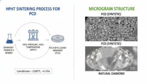
Découvrez ce qu’est le diamant polycristallin, ses principales applications industrielles et les conseils d’experts pour vous approvisionner et réduire vos coûts d’usinage.
Voir les détails
Polycrystalline diamond, commonly referred to as PCD in the industry, is an ultra‑hard material formed by sintering a large number of fine diamond grains under high temperature and high pressure. It retains diamond’s near‑ultimate hardness and wea...
Voir les détails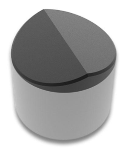
Kingpdc présente un type de foret Pdc - des fraises commerciales Pdc en forme d'arête qui peuvent être utilisées comme outils pour l'exploitation pétrolière.
Voir les détails
Optez pour des forets diamantés polycristallins PDC haut de gamme afin d'améliorer le débit de forage (ROP) et de réduire les coûts cachés liés au forage.
Voir les détails