 kingpdc




recherche de produits
recherche
PRECISION-CONTROLLED DRILLING CUTTER
Series: Precision Series
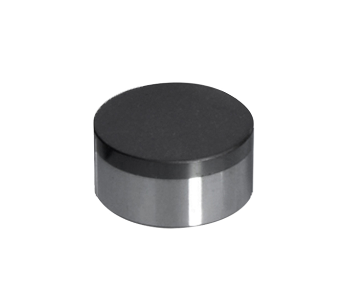
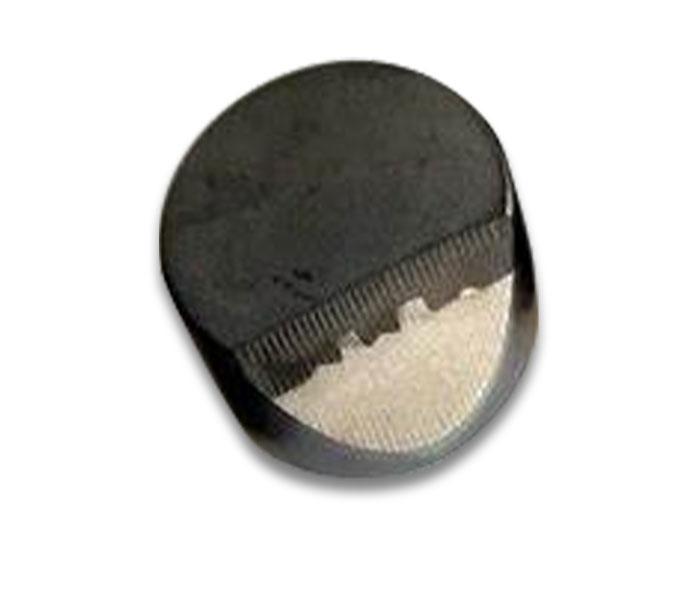
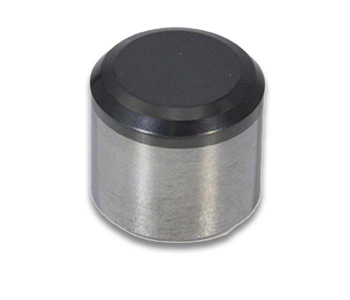
Precision PDC Cutter is a PDC cutting element for drilling, mining and engineering tools, supplied as a PCD diamond table bonded to a cemented-carbide substrate. Field Diamond controls size, chamfer and surface-finish requirements against the selected drawing so buyers can align pocket fit, cutter position, inspection records and repeat supply in one quotation.
DECISION SUPPORT
Precision is a measurable manufacturing and acceptance attribute—not a geometry name. Freeze the controls below before comparing quotes.
| Reference package | 13.44 × 13.20 mm; diamond-table height 2.00 mm |
|---|---|
| Dimensional limits | Diameter ±0.03 mm; total height ±0.10 mm; diamond-table height ±0.20 mm |
| Chamfer limits | Chamfer size ±0.05 mm; angle ±1° for the documented 13 mm-class package |
| Impact of tighter limits | Tighter limits improve pocket fit and batch consistency but increase machining, measurement and sorting effort. |
| Best fit | Use the reference package for standard 13 mm-class cutters; use a drawing and inspection plan for shaped, press-fit or automated assembly programs. |
Freeze nominal values, upper and lower limits, datums, measurement method, sampling and batch-report fields before requesting a production quote.
DECISION SUPPORT
Choose the cutter profile from the bit position and formation first, then lock precision, chamfer and pocket fit as one controlled specification.
Uniform shear and simpler pocket geometry for soft-to-general formations.
Stress-distribution and impact-margin option for abrasive or hard-rock positions, with geometry-specific pocket and inspection requirements.
Flat profiles simplify a uniform cutting path. Shaped profiles can improve impact margin but require matched orientation and pocket controls.
Start from cutting position and formation; then release geometry, dimensions, chamfer, mounting interface and inspection criteria together.
COMPLETE SPECIFICATIONS
Use the reference package for a 13 mm-class cutter or release the final dimensions against the buyer drawing revision.
| Product name | Fraise PDC de précision |
|---|---|
| Model / part number | Precision Series; final dimensions and chamfer profile are drawing-controlled |
| Product category | PDC cutting element for drilling, mining and engineering tools |
| Nominal size | Standard base diameters 8.00–25.40 mm; reference 13.44 mm diameter × 13.20 mm total height |
| Size tolerance | Reference diameter ±0.03 mm; height ±0.10 mm; diamond-table height ±0.20 mm; chamfer size ±0.05 mm; angle ±1° |
| Material / composition | PCD diamond layer bonded to a cemented-carbide substrate; optional leaching by specification |
| Connection / interface | Brazed or pocket-mounted cutter; carbide base and brazing face cleaned before joining |
| Applicable standard | Drawing-controlled product specification; ISO 9001:2015 quality-management system |
| Marking / traceability | Model or drawing revision, batch, sample and inspection date recorded with the production report |
| Packaging unit | Individual protective packing in export cartons; quantity and label format recorded with the order |
APPLICATIONS & EQUIPMENT
Match cutter geometry, diamond-table exposure and carbide-base interface to the bit position and formation.
Primary or gauge positions in tight oil and gas, shale, interbedded and deepwater formations; select flat or chamfered geometry with the bit designer.
Drilling tools where cutter geometry, diamond-table exposure and the carbide-base interface are matched to hard rock, abrasive rock and the designed cutting path.
Submit the pocket drawing, nominal size, chamfer, material stack, quantity and inspection requirements for a comparable custom or replacement quotation.
TECHNICAL DRAWING
Use the reference drawing view to start a discussion; final geometry, datums and tolerance are released against the buyer drawing revision.
MATERIALS & PROCESS
PCD-on-carbide construction is processed through controlled synthesis, machining, finishing and inspection stages.
PCD diamond table bonded to a cemented-carbide substrate; grade and optional leaching route selected against formation and thermal requirements.
Raw-material inspection, assembly, HTHP synthesis, rough and precision machining, chamfering, polishing, quality inspection, packing and shipping.
Precision grinding, chamfering and polishing, followed by dimensional, surface and internal-integrity checks against the drawing.
PERFORMANCE & CONDITIONS
Reference test stages and dimensional data support selection; they are not a universal operating rating for every bit design.
CUSTOMIZATION
Share the drawing revision and target quantity so geometry, process route and acceptance records can be quoted together.
USE & SAFETY
Use trained personnel and the approved bit drawing and drilling program for the selected cutter geometry.
Verify drawing revision, dimensions, chamfer and batch label. Clean the carbide base and bit brazing face with acetone or alcohol for 2–4 hours, or use an ultrasonic cleaner.
Use Bag-24 silver-based braze at 670–730°C for 10–15 seconds. Align the cutter in the pocket and cool slowly in an insulated box; do not water-quench or oil-quench.
Stop about 0.2–0.3 m above hole bottom, circulate flushing fluid or air, then make first contact at 30–60 rpm. Run 1–2 tonnes at low WOB or the corresponding start load over 0.2–1 m before full load.
Inspect after brazing and break-in for cracks, delamination, abnormal edge damage and pocket movement. Keep unused cutters dry, protected from impact and traceable to drawing revision and batch.
PURCHASING CONDITIONS
Commercial terms are set from model, drawing revision, grade, quantity, inspection plan and delivery destination.
PRE-SALES & AFTER-SALES SERVICE
Keep the drawing, inspection record, batch label and delivery documents together for repeat orders and technical follow-up.
Review the drawing, bit position, formation, nominal size, chamfer, grade and inspection plan before quotation.
Align sample approval, precision inspection, batch traceability, packing label and shipping documents with the order.
Receive installation guidance, technical support and repeat-order handling; quality-related unusable product is eligible for replacement under the stated service boundary.
FACTORY & MANUFACTURER
Wuhan Field Diamond Co., Ltd. supports PDC cutter development, manufacturing, processing and supply from Wuhan, Hubei.

Founded in 2018, Field Diamond covers PDC cutter R&D, HPHT synthesis, precision machining, chamfering, polishing, inspection and supply, with custom sizes and geometry discussions for drilling, mining and engineering tools.
CERTIFICATES & STANDARDS
Management-system evidence is shown separately from the product drawing and inspection plan.

REQUEST A TECHNICAL QUOTE