 kingpdc


búsqueda de productos
busque en
This selected range shows how flat and shaped PDC cutter technologies address general cutting, directional edge work, and point-loaded rock engagement while helping engineers balance penetration, torque, heat, impact, and bit-position requirements. Standard sizes, drawing-based profiles, engineering samples, inspection evidence, and defined order terms turn formation and bit-design inputs into a production-ready quotation. A polycrystalline diamond table bonded to carbide shears rock continuously, while grade, interface, chamfer, and geometry manage wear and failure risk.
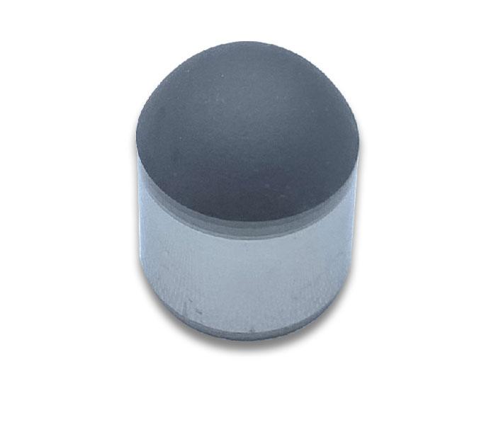
This selected range shows how flat and shaped PDC cutter technologies address general cutting, directional edge work, and point-loaded rock engagement. Geometry should be evaluated with cutter diameter, orientation, bit layout, formation abrasiveness, impact severity, and hydraulic cleaning.
| Cutter geometry | Rock engagement | Typical position or use | Formation fit | Primary benefit | Main tradeoff |
|---|---|---|---|---|---|
| Fresa plana PDC | Broad, predictable shearing face | Primary or gauge cutting | General oil, gas, water-well, and coal-mining service | Stable baseline for layout and grade trials | Less localized loading than shaped profiles |
| Con forma de filo | Localized edge engagement | Directional or gauge-control work | Directional and shale-gas applications | Supports targeted cutting and lower-torque strategies | Orientation and placement need bit-level validation |
| Forma triangular | Point loading along three inclined faces | Primary cutting in high-engagement zones | Hard, interbedded, or impact-prone rock | Multi-edge engagement and chipping control | Concentrated loading raises sensitivity to layout and brazing |
Start with a flat face for a predictable benchmark, use a cutting edge where directional engagement or gauge control matters, and evaluate the triangular profile where concentrated multi-edge loading is useful. Validate the selected cutter in the complete bit design before production release.
A useful RFQ defines the cutter and the duty together. Its input package includes the product name or drawing, diameter and height with tolerances, diamond-table thickness or grade, face geometry, diamond and carbide chamfers, substrate or interface requirement, bit position, formation, abrasiveness, impact severity, WOB/RPM context, brazing or interference-fit method, and annual quantity.
kingpdc can review standard sizes or drawing-based profiles, then plan 1–5 engineering samples. Approval evidence can include dimensional inspection, C-scan ultrasonic integrity checks, and application-relevant wear, impact, or thermal tests; agree any X-ray or cobalt-leach verification before production.
HPHT synthesis bonds the diamond table to the carbide substrate. Precision grinding, EDM or laser shaping, chamfering, and polishing establish the final geometry. A standard production cycle is normally 7–15 days after approval; MOQ, packaging, EXW/FOB/CIF terms, and export documents are confirmed in the quotation.
A PDC cutter combines an intergrown polycrystalline-diamond working table with a tungsten-carbide substrate that supports the cutting face and provides a brazable base. The bonded interface transfers stress between materials with very different stiffness and thermal behavior.
During HPHT synthesis, diamond grains bond under approximately 60,000–80,000 atmospheres and 1400–1500°C (2552–2732°F). In the finished fixed-cutter bit, rotation keeps the face in contact with the formation so it removes thin layers by shearing instead of the repeated crushing action of a roller cone.
Technology variants exist because no single grade or face suits every interval. Diamond grade, table thickness, leaching, chamfer, interface design, and face geometry are balanced against abrasion, heat, impact, chipping, delamination, torque response, and the required drilling distance.
These featured flat and shaped PDC cutters cover predictable shearing, directional edge work, and concentrated multi-edge engagement. Geometry selection considers cutter size, bit position, formation abrasiveness, impact severity, and brazing constraints together.
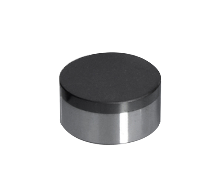
A stable baseline for oil and gas, water-well, and coal-mining bits where predictable shearing is the priority.
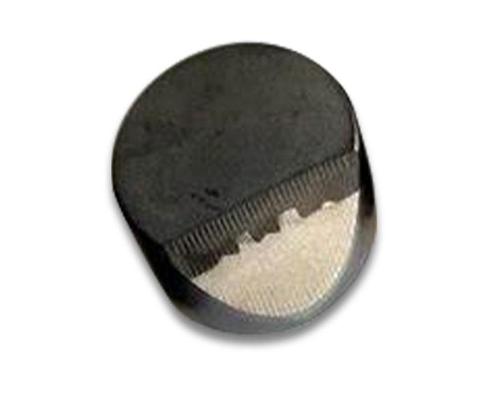
For directional drilling and shale-gas bit layouts that need localized edge engagement at primary or gauge positions.

For hard or interbedded formations and tunnelling tools where multi-edge point loading and chipping resistance are evaluated.
Commercial terms below are practical starting points and are confirmed against geometry, test scope, quantity, and destination in the formal quotation.
1–5 pieces; quoted by geometry and test scope; typical review and sample cycle 7–10 business days.
From 50 pieces per geometry and size; quantity-based unit pricing, dimensional inspection, and labelled packing.
Volume pricing and capacity reservation are confirmed against forecast, approved sample, and call-off schedule.
Standard production lead time is normally 7–15 days after technical and commercial confirmation.
EXW, FOB, or CIF by agreement; DHL/FedEx for samples and air or sea freight for production lots.
Commercial invoice, packing list, and agreed inspection report; request extra test records before confirmation.
A complete review package includes a dimensioned profile plus formation, bit position, brazing method, target quantity, and any inspection requirement. Engineering review confirms feasibility, tooling, sample scope, and production terms.
Process limits, support, and documentation are confirmed before cutter or lot approval.
A controlled brazing temperature of 670–730°C (1238–1346°F), a heating period of about 10–15 seconds, and slow cooling are recommended. The final cycle is verified against the bit body, filler alloy, and cutter grade.
kingpdc provides a 12-month warranty for verified manufacturing-quality issues and can arrange replacement after the affected lot, operating record, and failure evidence are reviewed.
Remote failure-analysis support can begin within 48 hours after receipt of clear photos, cutter position, run data, formation description, and the affected lot or packing reference.
Dimensional inspection and agreed test records can be supplied with the lot. Request any C-scan, wear, impact, thermal-cycle, X-ray, or material evidence in the purchase specification so the exact document set is confirmed before production.
Yes. A complete review package contains the profile, tolerances, diamond-table and chamfer requirements, carbide interface, brazing constraints, bit position, formation, and forecast quantity. Engineering review determines tooling, sample scope, test plan, MOQ, and lead time.
Include geometry, dimensions, formation, bit position, quantity, and target delivery date.