 kingpdc




búsqueda de productos
busque en
Fitting shaped cutters, adding a row of backup cutters, or choosing a more wear-resistant material can all change a PDC bit. A structural change, however, does not necessarily solve the original problem. To judge whether an advanced pdc tool suits a target interval, consider the loads the change addresses and how it works within the complete bit, rather than relying on a cutter shape name alone.
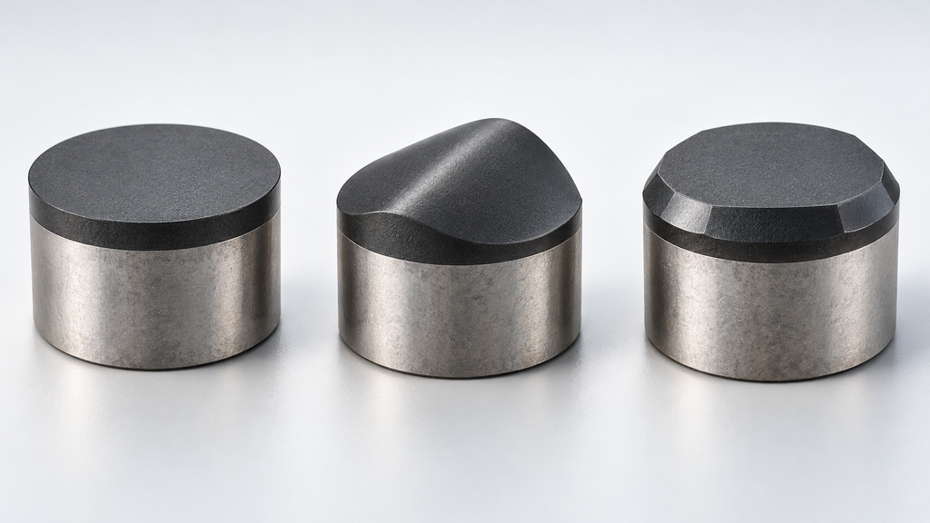
Gradual dulling caused by abrasion and sudden edge damage caused by hard interbeds place different demands on an improvement. Wear resistance, impact resistance, and thermal stability are separate performance dimensions. Improving one does not automatically improve the others.
Outer cutters travel a longer path per revolution and may accumulate more wear, but the same positions can also experience lateral vibration and impact. Cutters meeting hard interbeds face transient changes in depth of cut, torque, and loading. In soft, plastic formations, cuttings movement, cleaning, and bit balling also matter; material hardness may not be the first factor limiting drilling.
Design objectives involve trade-offs. Higher rate of penetration, longer footage per run, borehole quality, and improved stability do not necessarily come together. Drilling speed and service life can constrain each other. Assessing a proposal using only average formation strength can miss the changes introduced by interbeds and heterogeneous intervals.
PCD means polycrystalline diamond material, while PDC means polycrystalline diamond compact. A typical PDC cutter consists of a diamond working layer, a cemented-carbide substrate, and their bonding interface. It is one element in the complete bit’s cutting structure. The bit body, blades, cutter layout, gauge structure, and hydraulics all contribute to actual performance.
A thicker diamond layer can provide more material available for wear, while also changing residual stress, the heat-transfer path, and impact response. Material-grade selection therefore relates to the loading at each cutter position. Long-path wear, high vibration, and insufficient cooling point toward different improvement priorities.
Cutter geometry must also be understood in its installed position. A ridge-shaped cutter changes contact and rock-breaking behavior; the orientation of its ridge relative to the cutting direction affects how it engages. A double chamfer adjusts initial impact protection and subsequent cutting response, with its effect depending on the actual dimensions and depth of cut. Names such as 3D and 4D generally identify a manufacturer’s structure or product series. Actual geometry, orientation, and operating conditions explain more than the name itself.
The same shaped cutter may perform different duties at the center, shoulder, backup row, or gauge area. Changes in installation angle, orientation, exposure, and support also change the working edge and trajectory coverage. Cutter diameter should not simply be treated as the effective cutting-edge width.
Backup cutters can share loading, provide redundancy, remove ridges, or take over as primary cutters wear. Their position and relative height determine how they participate. Depth-of-cut control elements have a different duty: limiting local penetration to control overload and torque surges. Neither arrangement is merely an increase in primary cutter count. A control element that sits too high may rub continuously against the bottom, while one that sits too low or follows an unsuitable trajectory may fail to limit penetration in time.
More blades and cutters generally help distribute loading, but may narrow the flow passages between blades and increase contact and friction. The potential for multiple rows to extend the usable cutting stage also comes with the cost of occupying cuttings-removal channels. Added backup cutters, control elements, and wear blocks change local flow conditions as well.
Hydraulic matching must reach the individual cutter positions. Nozzle placement, blade obstruction, and the direction in which cuttings leave jointly affect cleaning. Total flow and pressure drop do not describe the cooling available to every critical cutter. Thermally stable cutters can provide greater tolerance to heat loads, but adequate local flow and cuttings removal remain separate design requirements. Evaluating materials, cutter layout, and hydraulics independently can overlook the constraints between them.
Material tests compare wear resistance, impact resistance, and thermal stability. Single-cutter tests evaluate cutting response. Multiple-cutter trajectories, overall torque, and wear distribution belong to complete-tool validation. A good single-cutter result is not sufficient on its own to establish the stability of a full bit. Predictions from simulation also need to retain their input conditions and assumptions.
When comparing total footage or average rate of penetration before and after a change, the interval, formation, operating parameters, and reason for pulling the bit must correspond as well. If geometry, material, and cutter layout change together, it becomes difficult to attribute the result to a new cutter shape alone. Before adopting an improvement, check whether validation covers the target conditions and whether the evidence supports the required drilling-speed, footage, or stability objective.
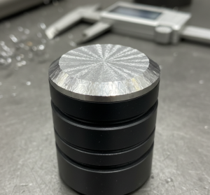
Sepa cuándo reparar o desechar una broca PDC. Nuestra guía de expertos le ayuda a reducir costes y a elegir el servicio de reparación adecuado.
Ver detalles
Descubra qué significa la broca PDC. Domine la forma completa, la información vital, la pirámide TEH y los datos de matriz vs acero.
Ver detalles
El distribuidor de brocas PDC escalonadas le enseña a elegir la broca PDC adecuada en función de los escenarios y las condiciones de trabajo.
Ver detalles
Ver el dibujo acotado del engranaje de corte PDC. Conozca las especificaciones y tolerancias estándar y haga su selección.
Ver detalles